
CAREER ACCELERATOR PROGRAM
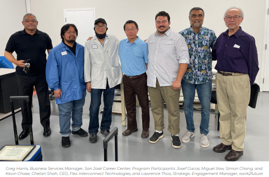
On August 12, 2022, teams from work2future, Evergreen Valley College, and Flex Interconnect Technologies (FIT) gathered to celebrate the successful conclusion of a 10-week training and work-experience program. The event featured four newly graduated trainees, each one the recipient of a full-time job offer at FIT.
This innovative EARN & LEARN program was made possible by the Workforce Accelerator Fund 9.0, a California Workforce Development Board grant program designed to give local workforce development boards funding and flexibility to bridge current gaps in the workforce system, with a meaningful focus on creating employment pathways to good quality jobs for workers from disadvantaged or low-income communities.
The local program, developed by work2future and Evergreen Valley College, paired classroom training with real-world hands-on work experience – and gave participants a steady paycheck and other support services. Michael Hernandez, Adjunct Professor at Evergreen, called the program “a model for industry and education” and noted that its success was due to the truly collaborative efforts and an across-the-board buy-in from program participants, the employer management team, school administrators and department heads, and local workforce professionals.
work2future, a Workforce Development Board in the San Jose/Silicon Valley area, served as both program coordinator and funding manager for the effort. Strategic Engagement Manager Lawrence Thoo led the team which brought together key resources to support the larger program effort: building a learning and training program customized to meet FIT’s needs, recruiting 25+ applicants for the program, underwriting and administering payroll, and completing all reporting requirements.
The four selected trainees completed rigorous Advanced Manufacturing coursework on campus and at the work site. Mr. Hernandez worked closely with FIT CEO Chetan Shah to tailor the assignments to closely align with the participants’ daily work. For trainees who choose to continue their education, these college-level courses can be applied toward an Advanced Manufacturing Level 1 Certificate.
At FIT, department managers worked closely with individual trainees, modeling an open work environment with direct one-on-one training and space for ongoing feedback, support, and discussion. As a final project, the trainees were asked to create a presentation for the FIT management team about the practical applications of their training and recommendations for policy and procedure updates. At the end of the 10-week program, the team at FIT felt confident in the skills and potential of each participant, offering them full-time, benefited employment.
Career-accelerating programs like this one provide opportunities for workers to confidently step into new employment pathways and enable businesses to work with talented people from diverse backgrounds. This successful effort paves the way for expanded EARN & LEARN programs benefiting workers and employers alike.
For more information about Work2Future Earn & Learn Career Accelerator Programs, or employment opportunities at FIT, please send your resume to [email protected].

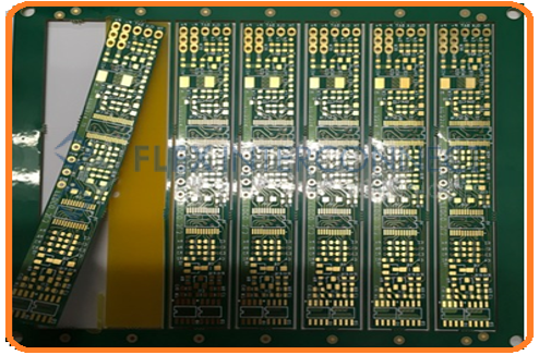
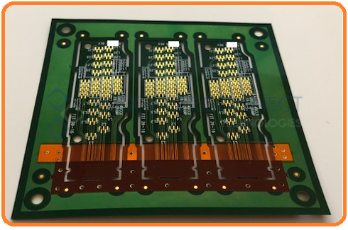
TYPES OF FLEXIBLE CIRCUIT DESIGN
Flex Circuits has a variety of design options depending on the complexity of interconnect needed – from single sided to multilayer flexes to rigid-flex hybrid. Designs are customized with variety of copper weights, plated-thru holes, number of layers, and laminate types and thicknesses, depending on the application needs. Several termination options such as ZIF fingers, SMT or Thru-hole connectors, Sculptured fingers, can be utilized to best fit your product requirements.
To learn more about Types of Flexible Circuit Design, contact us at [email protected]

BENEFITS OF FLEX CIRCUITS
Flexible Printed Circuits have been the enabling technology for creation of many modern electronic products such as laptops, mobile devices, medical devices, sensors, etc. Flexible circuits are made with thin flexible laminates which allows them to take any 3D shapes. They play a major role in saving space and reducing weight, thus enabling lighter and smaller devices. The flexible circuits materials have very good electrical properties that provides great signal integrity for high speed data transmission. In addition they are very reliable, creating a stronger and more reliable product.
To learn more about the Benefits of Flex Circuits, contact us at [email protected]

SAMTEC HIGH SPEED CABLE SOLUTIONS
Samtec is well known for their “SUDDEN” service model to support the customers’ small volume needs quickly and at a low cost. Based on this philosophy, Samtec developed several standard high speed datalink flex circuit solutions around their most commonly used connectors. Customers could order these cables directly from their catalog as a standard item with no minimum buy requirement. When Samtec existed their flex circuit manufacturing business in 2011, they transferred all their standard cable solutions to Flex Interconnect, since Flex Interconnect had been the flex circuit manufacturing partner of Samtec since 2002. These standard cable solutions are now available through Flex Interconnect without incurring any NRE cost of designing and producing custom cable. Details about the cables and their specifications are available at www.FIT4flex.com/samtec.
To learn more about SAMTEC high speed cable solutions, contact us at [email protected]

ICT HINGE BENEFITS
As electronic devices become smaller, thinner and more compact, there is need for flexible printed circuits to be able to make tight bends to fit into tight spaces. Traditional flex circuits are limited to minimum bend radius of 10X to 15X the thickness of the flexible circuits depending on the number of layers. Infinite Corridor Technology (ICT) founded in MIT, has developed a unique ways of producing flexible circuits that allow them to bend up to 8 times tighter than traditional flexible circuits. This involves utilizing custom hinge design into existing flex circuit profile to allow greater flexibility and tighter bendability, and reduced stress on copper traces. It also reduces weight and improves the air flow in the package. Unique applications in the wearable electronics space is achievable with ICT hinge technology, that traditional flex circuit technology will not be able to solve.
To learn more about ICT hinge technology, contact us at [email protected]
UNDERSTANDING COST DRIVERS
Understanding common cost drivers prior to beginning your design can be invaluable when trying to build a reliant but cost effective circuit.
Basic Cost Drivers
- Material Utilization
- Layer Count
- Basic Complexity: Avoid anything less than 3/3 mil spacing with 5 mils on outer layers of rigid-flex, vias smaller than 8 mils, or fine lines/spacing in relation to the length of the trace
- Multiple surface finishes on same part
- Special Material: Consider the polyimide cores you’re selecting. Non-standard core thicknesses will be more expensive, along with thicker kapton or copper
- Special stiffener materials: Standard stiffener material is FR4. There is additional costs ceramic or metal stiffeners such as stainless steel or aluminium
Cost Adders
- Blind/Buried Vias
- Via Fill and Via-in Pad
- Class 3 which requires serialization, multiple cross sections, coupons, and outside lab testing
- Laser processing needed with microvias, laser skiving, masked defined pads, and tight tolerances
- New Technology and Materials
ASSEMBLING FLEX CIRCUITS
FLEX ASSEMBLY TIPS :
Array Options:
There are many ways to panelize a flex circuit for assembly. For your array design keep in mind the following:
- Tab routing is the best way for flex, instead of scoring
- Use local fiducials within the flex circuit
- Use lots of copper for stability
- Optimal sizes depending on the size of the flex and component feature. We recommend: 5 x 5”, 5 x 10”, 8 x 10”, 10 x 10”, 10 x 16”
- Methods of singulation of parts: Xacto knife, Laser cutting, Die-Punch, Routing
- Singulation process should not induce stress in the solder joints
Fixturing is very essential when assembling flex. Due to material movement and fine pitch devices, proper fixturing is required. The benefit of fixturing are:
- Ability to assemble singulated flexes with precision
- Lowers the fab cost since manufacturer can utilize their material efficiently
- Part to part variability in array due to material movement is eliminated
- It helps automating the assembly process, instead of hand placement of parts, and thus reducing cost of assembly
- Greatly improves quality of assembly and reduces need for rework and touch up
Here are some different array examples:
Here are some different fixturing examples:
Guide to ordering Stencils:
- Typically 4 mil or 5 mil thick
- Occasionally 3 mil thick or step down stencil may be needed
- Coated stencil needed for micro BGA
- Add fiducials on stencil to align properly
- Mini stencil for offline printing is commonly utilized and sometimes components are loaded by hand
- Stiffeners or FR-4 guides are used to align mini-stencils
Baking Guidelines:
- Polyimide laminates and adhesives absorb up to 3% by weight of moisture
- All flex circuits should be prebaked at 125℃ for 2 to 6 hours
- Moisture uptake for Acrylic adhesives at 80% relative humidity and 23℃:
● 0.65% by weight in 2 hours
● 1% in 10 hours
● 1.2% in 2 days
- Moisture in flex creates very high vapor pressure during re-flow and possible delamination:
● At 220℃ the vapor pressure of water is about 340 psi
● At 230℃ the vapor pressure of water is about 400 psi
● At 260℃ it increases to approximately 700 psi
- Maximum storage time at 50% humidity is 8 hours
Reflow Parameters:
- Ramp rate is slower, approximately 2.5℃ per second
- Peak temperature for pure flex for RoHS assembly is 225℃
- Soak time is kept at minimum – 30 seconds or less
- Rules for rigid-flex are similar to rigid PCB
- Always use thermocouples to profile the reflow oven
Challenges you can expect with assembling Flex:
- Dimensional stability of the flex material – thinner is worse
- Warpage or deformation after one side assembly
- Registration of solder paste
- Pick and Place programming – sometimes have to manually teach each array at a time if proper fiducials are not present
- Handling
- Moisture
- Solid copper shields
- Component Misalignment
- Rework
- Productivity and Cost – NRE and labor costs are higher