
At Flex Interconnect Technologies, we pride ourselves on building and delivering superior flexible circuits. Achieving robust and reliable flex circuits goes beyond the material choice in the package. It is crucial that we understand the application of a flex circuit to determine the proper design attributes that will be required to attain the best structural integrity. One such critical attribute is bend radius, which we’ll discuss in detail in the following.
The Bends and Stresses of Flex Circuitry
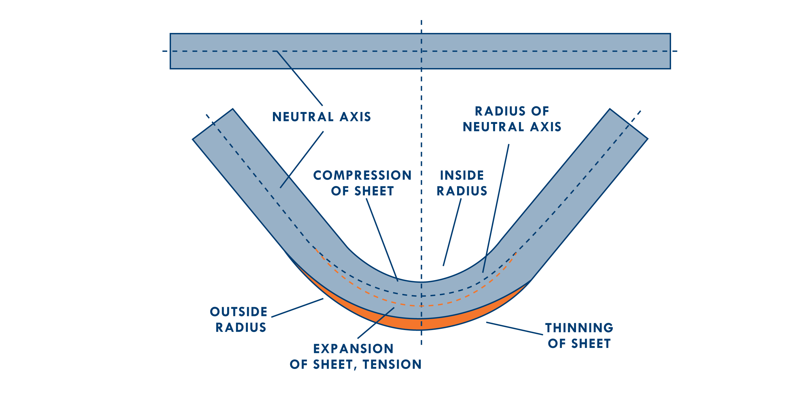
When measuring the minimum bend radius in flexible circuit boards, a crucial factor is the neutral axis. This imaginary line within the material experiences neither compression nor stretching during the bend. By basing the bend on the radius of this neutral axis, we ensure the outer material undergoes acceptable expansion, and the inner layer experiences controlled compression. Imagine this: you’re folding a piece of paper. The tighter the fold, the more stress it experiences. The same principle applies to flex circuits. Bending creates stress, which can lead to cracked traces and malfunctioning circuits.
Bend radius defines the minimum allowable bend for a flex circuit without compromising its integrity. In other words, it defines how tight you can bend your flexible circuit. Here’s a quick guideline to consider…
- Single-sided copper: 3-6 times the thickness
- Ex: 4.5 x 4.5mil = 20.25mil or 0.02in minimum radius
- Double-sided copper: 8-10 times the thickness
- Ex: 9 x 8mil = 72mil or 0.072in minimum radius
- Multilayer circuits: 10-15 times the thickness
- Ex: 12.5 x 35mil = 437.5mil or 0.438in minimum radius
With the above examples, you can see that the minimum radius for a double-sided copper circuit is approximately 3.5 times larger than for a single-sided copper circuit. Engineers designing for tight spaces may opt for a loose-leaf approach to multi-layer circuits instead of a multi-layer approach.
Understanding The Geometry
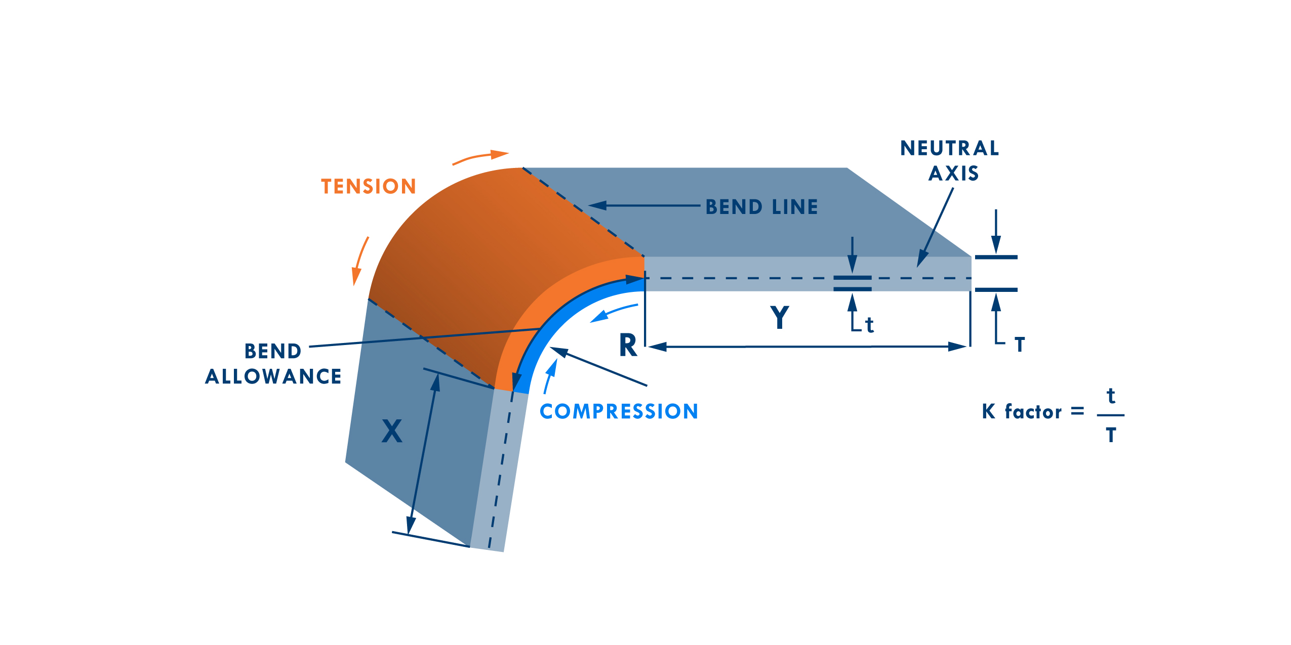
To understand the geometry you are bending, you first need to learn about bend allowance. Bend allowance is the extra length of material needed to account for the material stretching on the outside of the bend and compressing on the inside of the bend when a sheet of metal is bent. The simplified image below illustrates what happens as we bend the plane of a circuit.
- Tension: This is the side of the bend that stretches when the metal is bent.
- Bend line: This is the line where the metal is bent.
- Neutral axis: This is the imaginary line in the center of the bend that does not
stretch or compress. - Compression: This is the side of the bend that compresses when the metal is bent.
- Bend allowance: This is the extra length of material that needs to be added to the metal before it is bent to account for the stretching on the tension side.
Taking Design a Step Further
But bend radius is just one piece of the puzzle. Work with a manufacturer to make sure you are considering the following:
- Trace Routing: In rigid-flex circuits, avoid stacking traces to prevent stress during bending. Staggering traces distribute stress more evenly, creating a more reliable and durable design. For optimal flexibility in your design, ensure all corners, edges, and traces are smooth and rounded. Additionally, all pads should incorporate teardrops or fillets for reinforcement and utilize anchor pads for additional stability.
- Material Choice: Depending on whether the application involves static or dynamic bending, your manufacturing partner might recommend specific materials for optimal performance.
- Grain Direction: Rolled anneal copper offers a grain structure aligned with the bending direction of your circuit, allowing for better elongation and reduced stress compared to electro-deposited copper commonly used in rigid circuits. Make sure you work with your manufacturing partner to align grain direction with the grain structure of copper.
- Rigid-Flex Transitions: Transitions from rigid to flexible circuits are especially prone to high stress. Whenever possible, try to ensure a smooth transition from the rigid portion of your circuit into the peak bend of your flexible circuit to alleviate the stress on that transition point. This will prevent the flex from taking the brunt of the stress at the connection point.
- Epoxy Beads: The transition zone between these sections is a critical point where stress can concentrate on the copper traces, potentially leading to fatigue and failure. Epoxy beads are a valuable tool for mitigating this stress and ensuring the long-term reliability of your rigid-flex design.
- Gradual Transition: Epoxy beads are applied as a tapered fillet along the edge of the rigid section, adjoining the flexible area. This creates a smooth transition zone instead of a sharp bend. The gradual change in curvature distributes the bending forces more evenly, reducing the peak stress on the copper traces.
- Reinforcement: The cured epoxy material acts as a reinforcing element, providing additional support for the flexible area during bending. This helps to maintain the integrity of the copper traces and reduces the risk of fatigue cracks.
- Strain Absorption: The flexible nature of the cured epoxy allows it to absorb some of the bending energy, further reducing the stress experienced by the copper traces.
By understanding these design considerations and working closely with our customers, we can create flex circuits that bend with ease and deliver long-lasting performance. Remember, the more information you share about your application, the better we can tailor the design to meet your specific needs.
Please contact us and let’s work together to create a superior flexible circuit board that will function flawlessly, bend after bend. Contact us information and location | Flex Interconnect (fit4flex.com)